THE CASH RAILWAY WEBSITE |
||||||||
| Home | Manufacturers | Cash Balls | Wire systems | Cable systems | Pneumatic systems | Locations | References | Patents |
Pneumatic Tubes
The pneumatic tube was introduced into department stores in the 1880 by John Wanamaker, the Philadelphia retail magnate (Golden book of the Wanamaker stores, 1911, p.68). He had previously installed such a system in the US Post Office while he was postmaster general. The Manufacturer and Builder (Jan. 1881) states that there were two tubes to each counter - one for each direction. Each carrier was of the exact diameter of a silver dollar and could hold 30 such coins (so the tubes must have been quite narrow compared with later systems). "By means of steam engine and exhaust pump in the cellar, with proper attachments leading therefrom, the air is being constantly exhausted at the cashier's end of the tube and the counter end of the tube of each pair." The system was also claimed to improve the ventilation of the building.
An article in the Dundee Advertiser, 2 November 1880, described the use of a pneumatic tube system in large American "drapery and similar stores" though without mentioning names. "A steam-engine in the cellar keeps up a constant pressure of air by exhausting the tubes... The plan is said to be economical, but at any rate it avoids the noise and bustle of the old system of 'cashiers' or 'cash here!'" A similar article appeared in the Belfast Evening News three days later which commented "It will be odd if a good many of the busiest of London retail houses do not adopt it."
One early installation in England was the system in Bainbridges of Newcastle, the invention of Mr John Newton, foreman with Messrs Henry Walker and Sons. Newcastle Evening Chronicle, 21 Oct. 1886, p. 4. In 1888 a bronze medal was awarded to the company (based at Westgate Road) for the 'Newton-Walker' Pneumatic Cash Carrier. Shields Daily News, 8 Feb. 1888, p. 1. The first 'Electro-Pneumatic Cash Carrier' in Scotland was claimed to be at Thomas Blakeney & Sons of Dundee, invented by Mr W.H. Blakeney. Dundee Advertiser, 21 Sep. 1887, p. 9
Pneumatic tubes had already been used for other purposes for many years. John Griffiths credits the invention of pneumatic message systems to William Murdoch, 1754-1839.
The vacuum plant usually consisted of a large fan, driven by an electric motor or other power unit. The fan took the form of a large disc with a number of vanes radiating from its centre. This was enclosed in a casing with an inlet pipe at the centre and an outlet pipe on the circumference. When the rotor was revovled the air was flung outwards by centrifugal force into the exhaust pipe. Air was drawn in to replace it, so causing a vacuum in the inlet pipe, which was used to draw the carriers through the transmission tubes. Small systems might be powered by a set of bellows in a cabinet, operated by a foot pedal. The air from the bellows blew the carrier through the tube. Such systems were "in great demand for service between floors or rooms" Story of a service idea
As with wire systems, Lamsons dominated the market and took over many of their competitors. Their Bulletin Q-1 (ca. 1912) stated that a tube system costs more but does more than any other. Tubes are concealed, silent, automatic, and five times speedier than any other carriers. Nearly 50,000 stations were in daily service in "the best known and most progressive retail stores of the world". The cost of operation had been reduced by 60-90% by Lamson Power Control devices.
The standard tubes in shops are 2¼ inches in diameter. (This is the same diameter as used by the Electric Telegraph Company for their second tube in London in 1858. By 1870, 3 inch tubes were the norm for telegraph companies.) Bends can be as small as 12 inches radius, but such tight curves cause a drag on the system and special inspection covers should be fitted. Radii of 2 - 3 feet are generally desirable if the system is to be efficient and cheap Westwood and Westwood. "Judging from the systems used by Macy's, Gimbels and Altman's in the early twentieth century, a good-sized store needed from sixteen to eighteen miles of tubing." Whitaker.
The "independent system" employed two tubes to serve each station. This allowed sending and receiving at the same time, giving a faster service. Carriers could be sent at intervals of a few seconds and several could be in transit simultaneously. Memo from Lamson Engineering, 17 March 1953
Originally the working presure was maintained in the tubes at all times. However, this was inefficient and later systems allowed the motor to slow down when demand was lower and lines were closed down when no carrier was present. This is described in the following account from the Geelong Advertiser, 12 Mar. 1917, p. 2:
Messrs Bright and Hitchcocks have just installed the latest and most up-to-date system of cash carriers. It is the first installation of the kind in Victoria—there are only two others in Australia one being in the palatial Commonwealth Banking Chambers in Sydney... Messrs. Bright and Hitchcocks' old system ... consisted of a six horse-power motor and blower for 18 stations. Even when the tubes were not actually in use, there was a consumption of upwards of three break horse-power. Under the new system this is replaced by a variable-speed type of motor and blower, which is so controlled electrically that instead of working at a full speed of 100 revolutions per minute continuously, the blower may work down to 35 revolutions per minute. Where the old power plant was consuming three horse-power the new one is using less than one horse power. The controlling power is so elastic that by simply putting a carrier into the tube the motor speeds up to the amount of air required, and as carriers are added at the various sending points so the plant increases its capacity to accommodate any rush after which it reverts to the minimum speed... Now, until a carrier is inserted a tube is out of action altogether. The entry of the carrier releases an electrically-controlled catch.
The new cash transit system at Piggott & Co. in Toowoomba, Queensland, appears to be of this type and was the only one on the Darling Downs when installed. It had 13 stations and was described as the Lamson Independent Line Pneumatic Tube System with automatic control and was operated by a 2 h.p. electric motor. (Toowoomba Chronicle, 28 Jul. 1919, p. 5)
By the 1920s pneumatic tube installations were being used additionally for working vacuum cleaning systems. An article in the Western Daily Press, 15 Mar. 1928, p. 8, describes how the apparatus was used at Bobby's in Bristol for cash carrying in the daytime and vacuum cleaning at night.
Pneumatic tubes have been used more recently to carry surplus cash from the checkouts in supermarkets to more secure storage. These one-way systems generally use plastic carriers and uPVC tubing. See modern systems.
More details
Carriers | Early Terminals | Pneu-Art terminals | Cash desks | Other applications (outside shops)
Companies
Lamsons Dart Cash Sturtevants British Cash and Parcel Conveyors Modern systems
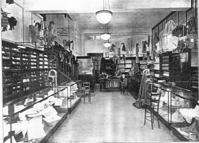
Two pneumatic tube stations in the drapery department of a store. Modern draper (London: Caxton, 1924) |
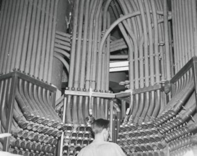
Despatch operator in Marshall Field, Chicago, 1947. Chuckman's Photos on Wordpress |